

"Power delivery: There are two specially made umbilical cables which provide the transmission from the separate power supply to the amplifier as well as a breaker-style power switch that protects the transformers and will trip in the event of a fault. There are also fuses for the 211/845 filament supplies, a fuse for the 1'100V B+ rail and one fuse on each output transformer primary for protection in the event of most possible faults like a blown power tube, a shorted filament, excessive heat or a failed rectifier, capacitor or damper tube or an AC short at the primaries on any of the transformers. The umbilical cables carry no less than six different voltages. The larger one carries 4 x 6.3V wires and 4 x 10V wires while the smaller one carries 1'100V, 420V, 216V and the system ground. It is very important that these connecting power umbilicals be fully inserted and twist-locked into place tightly before the amplifier is operated-s they are the lifeline between the amplifier and its power supply. It is also imperative that these cables not be disconnected for a full 5 minutes after the amplifier is turned off. Removing them prematurely can result in the two fuses inside the amplifier to trip due to micro arcs between the terminals. Those are 500ma fast-blow types that protect the output transformers.
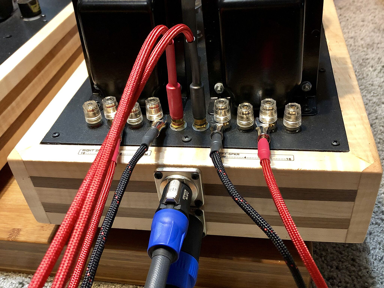
"Switching between the 211 and 845: Since the 211 and 845 have different output impedances, they have different output transformer requirements. The 211 requires around 10'000Ω as their anode load and the 845 about 5'000Ω. In order to have the same amplifier be able to run both, different impedance taps must be used when changing from the 211 to the 845. The 211 will use the taps as they are labeled behind the speaker binding posts (4Ω speaker on the 4Ω tap, 8Ω speaker on the 8Ω tap, 16Ω speaker on the 16Ω tap). For the 845 tube, these values must be cut in half so an 8Ω speaker would connect to the 16Ω tap, a 4Ω speaker to the 8Ω tap and a 2Ω speaker (or speaker whose impedance dips excessively at one frequency range or another such as planars) to the 4Ω tap. This protocol optimizes the operating conditions for each power tube type. In addition to the different speaker tap connections, there are two switches on the top of the amplifier that set the current for the power tubes (no other manual adjustment or biasing is needed). With the switches flipped back towards the rear of the amplifier, the amp is biased for 211. With the switches flipped to the front of the amplifier, it is biased for 845. These switches should only be changed with the amplifier turned off for at least 60 full seconds to ensure that all residual voltage has drained."


"Power delivery: The 211 can produce 25 continuous watts per channel, with peaks easily reaching 35 watts. The 845 can produce 35 continuous watts, with peaks over 40 watts given the conditions present in this amplifier. Many people actually listen at closer to 15-20 watts yet believe they are listening to 60-80 watts since wattage is not linear when increased. It actually takes twice the power to hear a difference of 3dB from your speakers. However with higher wattage, musical peaks and dynamics can bloom and create a larger soundstage with deeper insight to the musical content played. The current meters on the front panel monitor the plate current and will stay locked in place the entire time the amplifier is in Class A. During heavy transients or when the volume is cranked up, these meters will start to move as the amplifier goes into Class A2 and the 211 and 845 tubes draw grid current. The amplifier can reach up to a full 40 watts per channel with higher peaks of graceful overload when the meters are moving. This is far more powerful than a standard push/pull or solid-state amplifier of the same power and care must be taken to observe your woofers to avoid over-excursions especially with high-efficiency speakers!"

"Tube compliment: The front row of tubes in the amplifier are 6SN7 and the input voltage gain tubes. They run in SRPP or series regulated push-pull mode which puts the two halves of each tube in a 'totem pole' configuration. This provides low-impedance output along with medium gain to drive the input of the EL34 driver tubes and avoid slewing. Insure that the plastic guide pin on the bottom of the tube is centered towards the front of the amplifier. Damage can occur to the tubes and/or amplifier if the wrong type of tube is used and/or if the pin is not oriented correctly. The second row of tubes are the EL34 drivers for the 211 or 845. They are triode-strapped which lowers their output impedance and gives them the best linearity to drive the grid of the transmitter tubes. Please insure that the plastic guide pin on the bottom of the tube is centered towards the front of the amplifier. Damage can occur to the tubes and/or amplifier if the wrong type of tube is used and/or if the pin is not oriented correctly."

"The last row of tubes are the 211 or 845 transmitter power triodes. These have a pin located in the base that slides into the small groove in the metal base to then be rotated a ¼ turn clockwise until they lock into place. These tubes will get extremely hot under normal operation and must be cooled off for approximately 30 minutes before removing them. Also note that glass is fragile when hot so care should be taken to allow the tubes to cool before handling them."

