|
|
|
|
This review page is supported in part by the sponsors whose ad banners are displayed below
|
|
 |
|
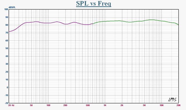
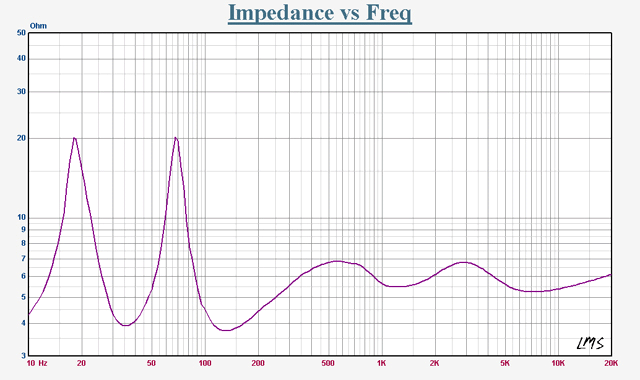
I asked Kim Neeper Rasmussen for an impedance vs. frequency plot to show load behavior for connected amplifiers. With the requested graphs, Kim sent the following comments: "Normally I don't do this since of course, you can always make a measurement look worse or better just by moving the microphone a few centimeters. The frequency response measurement was done in two steps. From 20kHz to 600Hz is a gated measurement. It is measured at 1 meter and 20 degrees off axis just above tweeter height. This is the vertical/horizontal angle from which the sound will reach the ears in an average setup. Below 600Hz down to 20Hz, the measurement was made at a half-meter distance without gating and smoothed to look closer at the nearfield curve of the drivers. I cannot plot the nearfield measurements into this curve and make it look realistic as there is a baffle-drop compensation in the crossover. Therefore, this doesn't look 100% as the measurement of the speaker would look in a gigantic anechoic chamber. The 20 - 600Hz level is around 1 to 1.5dB higher in reality but could not be cropped together as the end of the 600 - 20KHz slope was going downwards (600Hz is the end of what is possible to measure gated at one meter with a speaker of this height).
|
|
|
|
|
 |
|
|
"Regarding the crossover, people often misunderstand ScanSpeak drivers by looking at their measurements. Of course the static measurements don't look too good but there is a very good reason for this. ScanSpeak drivers are not developed to be super frequency linear. Their highest priority is dynamic linearity. A good example are the 15W drivers. All of them have something that can be easily thought of as a break-up. From 1 to 2kHz, output rises by 3dB. This is not a break-up mode but decoupled mass in the surround. When mass goes down, sensitivity goes up. The drivers I use extend straight to 8kHz without break-up but the frequency response doesn't look nice and has to be corrected in the crossover. This is also why a ScanSpeak-fitted speaker will never sound really good with a simple 1st-order crossover.
|
|
|
|
 |
|
|
"The crossover for the tweeter is electrically configured as a 4th order but it is very soft, rolling off around a 2nd order. A little thing about the ScanSpeak ring radiator is that it has very high sensitivity but you can never use all of it. It needs to be damped and controlled in the crossover. I use 14 components on the tweeter alone. Some people insist that the Vifa ring radiator is better than the ScanSpeak. This is simply not true yet with a simple crossover, the Vifa can in some cases sound better than the ScanSpeak. But do not blame the tweeter for user error. Likewise, the crossover for the upper mid/woofer is an electrical 3rd order but it also rolls off at around a 2nd order. The crossover on the lower mid/woofer is a 1st order, beginning its roll-off at 400Hz, very simple but the only way to get phase summation in a 2½ way design.
|
|
|
|
|
"So why all these components? As many would claim, the fewer components, the better the sound. I agree. 22 components are as few as it gets if you want to make a 2½ way speaker with ScanSpeak units and use them to their full potential. But if just one component value is wrong, you would be better off just using a 1st-order network.
"Without revealing all the secrets, I will give you a hint. Capacitors and inductors don't like each other very much. They need a 'middle man' before they agree to work together and pass music to the drivers. It's all about breaking down the Q values so that you get the needed roll-off without the higher-order tendency to either scream out loud or kill the music. It took almost a year, full time, before I was happy with it.
|
|
 |
|
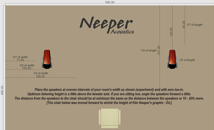
"I just saw your setup in the Acoustic System Tango review. I can say for sure that my speakers will not perform optimum in an identical setup. All speakers are a compromise, you cannot get everything. I developed my speakers 20 to 30 degrees off axis. The reason for this is that you have less diffraction from the baffle and less distortion from the drivers. It's not physically possible to get optimum phase summation both on and off axis with the deep cone geometry of the ScanSpeak 5½" driver. My suggestion would be that you either move the speakers closer to the listening position or the listening position closer to the speakers. Which works best is impossible to predict as it will depend on where the bass works best with the room. And use no toe-in at all. If my speakers are set up like the Tango, you will lack some midrange and have too much output in the top end.
|
|
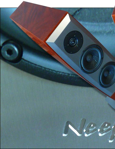
| "The bass reflex ports are tuned to the same 34/35Hz frequency as they are same length and the enclosure is not divided into several chambers. The reason is that the mid/woofers work in parallel at the bass frequencies and it's always best to have a |
 |
|
 |
|
chamber as large as possible for the midrange where resonances move down in frequency." I was still unclear on the crossover description as a '4th-order filter with 2nd-order attenuation': "The layout of the tweeter crossover includes 3 capacitors, 2 coils and 9 resistors. The schematic layout is 4th-order but as there are many resistors to control the resonances in the crossover, it rolls off very softly around a 2nd order. The phase rotation always follows the actual roll-off so the phase looks like a 2nd order crossover. The same happens with the mid/woofer.
"This is not a standard crossover you can look up in a book. It is customized to fit the drivers. The initial development for these types of crossovers comes from former ScanSpeak engineers. Again, why add 14 components to the tweeter when approximately the same roll-off and phase characteristics can be obtained with 1 capacitor, 1 coil and an L pad attenuation consisting of 2 resistors? 10 additional components distort the sound for no reason at all? Well, let's take a look at a 2nd-order high pass (low pass will react like it at the same crossover frequency if the driver has the same impedance) and forget about the tweeter for the moment. We see an amplifier, one capacitor and one coil. They are connected directly between the signal and ground (or positive and negative signal in a differential output stage). The capacitor is feeding the tweeter and the coil goes to ground to obtain the 12dB roll-off. |
|
 |
|
|
|
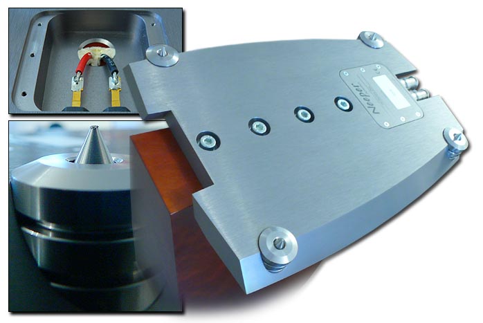
The only poorly engineered detail are the spikes. With the big lock nuts installed, they're plainly too short to be turned. Leveling the speakers in their intended place is a sorely frustrating exercise. It dances precariously between lengthening a spike with one hand, preventing the lock nut from retracting said spike when the nut is being tightened with the other, all the while balancing the quite tipped speaker with the body to prevent the crash. To not put too fine a point on it, this solution is a most royal pain in the arse, all in the name of designer cosmetics of course. No pain, no beauty. Women know all about it.
|
|
"A capacitor and coil connected together make a resonator by definition. Which frequency it rings at of course depends on the component values. As the output impedances of typical transistor amps are close to 0 ohms, the Q value of these resonators is very high to sound aggressive. Because music is not static sine waves, the actual behavior of the circuitry can be difficult to calculate. But you can definitely hear when you connect a combination of components that don't like each other. It just simply screams out loud. These ScanSpeak drivers need more than 1st-order roll-off to perform optimally. This way of breaking down the Q values is, I believe, the only way to get the needed attenuation and good sound at the same time.
"What I have is actually a time-coherent design. All drivers are in correct electrical phase. I personally can't stand listening to a speaker where the tweeter isn't in same electrical phase as the midrange. I think it loses the rhythm and realism. Of course there is some phase shift at the crossover frequencies which is intrinsic to all multi-way designs. My speakers need close to a 2-meter distance between the speakers and 1 meter to the side walls before they perform as intended. Also, they are developed to be very transparent, with realistic depth perspective. When your rear wall is 8 meters behind the speakers, it might end up being deeper than realistic. I used a 400-watt single Mosfet amp during development but also got great results with high-power Convergent Technology and VAC tube amps."
Likely surprising to Kim Neeper's power anthem, Canada's The Inner Ear Report obtained best results with their 32-watt Wyetech Labs Ruby SET monos over their massive 600-watt Bryston 14B SST muscle amp. To cover power consumption needs real and imagined, I'd run 15- and 18-watt triode monos (the parallel 300B Trafomatic Experience Reference and the 6C33S Ancient Audio Simple Six), the 25-watt First Watt F5 and the 300-watt Hegel H10 monster.
|
|
|
|
|
 |
 |
|
|
 |
|
|
|
|
|
|
|
|
|
|