This review page is supported in part by the sponsors whose ad banners are displayed below |
 |
 |
|
Technical specifications |
Conductors |
Signal: 0.51 mm silver plated 99.9997% pure copper
Power: 0.6 mm 99.9997% pure copper |
Connectors |
USB-A: 30µ 99.9% gold-plated A-grade phosphor bronze
USB-B: 30µ 99.9% gold-plated A-grade phosphor bronze |
Dielectric construction |
Layer 1: 0.55 mm gas-injected polytetrafluoroethylene
Layer 2: 0.08 mm biaxially-oriented polyethylene terephthalate
Layer 3: 0.32 mm gas-injected tetrafluoroethylene
Layer 4: 0.08 mm biaxially-oriented polyethylene terephthalate
Layer 5: 0.35 mm (+/- 0.1) polyvinyl chloride
Final dimensions: square-shaped 3.5 mm (+/- 0.1) X 5.0 mm (+/- 0.1) |
Rated bandwidth |
10.083Gbit/s |
|
 |
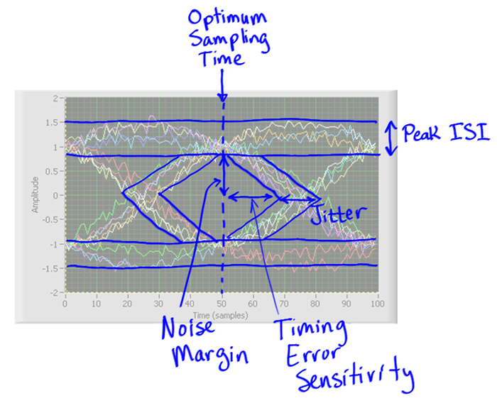
Included with each Lightspeed cable is a test report showing a variety of measurements including the aforementioned eye pattern. It would appear that based on its physical design and test measurements the Lightspeed has miniscule deterministic jitter as well as excellent rejection of common-mode and EM noise. I asked Larry Ho to provide greater insight on the Lightspeed’s measurements including the eye pattern measurement.
|
|
|
|
"The eye diagram or eye pattern is the graphical representation shown on a high speed oscilloscope's display of a digital data signal from a receiver which is repetitively sampled and applied to the vertical input. It is a common testing tool for high speed digital signal but not commonly used in the audio world. If the eye opening is wide enough, the signal is able to transmit under the given speed. In our test report it is 10Gbps. The eye diagram proved that our LightSpeed cable could be operated successfully with little distortion even running at 10G speed which is 20 x more than the USB 2.0 spec. The blurry part of the eye diagram is the 'evil' jitter of digital signal's rising or falling edges (the gray area inside the eye is the boundary and if the signal pattern touches that, it means signal failure).
|
 |
"A 2nd important factor I want to mention is the tightness of our impedance matching. Although the specs of USB 2.0 allow a +/- 10% variation in impedance, we only allow 1% to 1.8% of variance. The better matched the impedance, the less reflections of the transmission signal. This mean a more accurate bit-perfect signal with more accurate timing!
|
 |
|
|
|
"The 3rd factor is that the better USB cable, the less work the USB receiver IC does. The less work it must do, the more accurate the timing of each bit is which gets sent out. What does the USB receiver IC (PHY) do? Quite a lot. To avoid getting too technical, basically it needs to encode and decode the package by USB protocol in 480Mbps and translate that to the UTMI+ or ULPI interface. It consists of clock recovery and PLL as well as the control logic and it is much harder than people think. This complexity brings up a very important thing - the interface jitter for ULPI gets inherited by the actual music samples."
|
 |
  |
 |