|
This review page is supported in part by the sponsor whose ad is displayed above
|
||||||||||||||||||||
 |
||||||||||||||||||||
 |
||||||||||||||||||||
Reviewer: Srajan Ebaen Source: Zanden Audio Model 2000P/5000S Preamp/Integrated: ModWright SWL 9.0SE; Music First Audio Passive Magnetic Amp: 2 x Audiosector Patek SE run one channel each, the other shorted out; Yamamoto A-08S; FirstWatt F1 Speakers: Zu Cable Definition Mk 1.5 Cables: Zanden Audio proprietary I²S cable, Stealth Audio Indra (x2), Zu Cable Ibis, Zu Cable Birth on Definitions; Crystal Cable Reference power cords; ZCable Hurricane power cords on both conditioners Stands: 1 x Grand Prix Audio Monaco four-tier Powerline conditioning: 2 x Walker Audio Velocitor S Sundry accessories: GPA Formula Carbon/Kevlar shelf for transport; GPA Apex footers underneath stand, DAC and amp; Walker Audio SST on all connections; Walker Audio Vivid CD cleaner; Furutech RD-2 CD demagnetizer; WorldPower cryo'd Hubbell wall sockets Room size: 30' w x 18' d x 10' h [sloping ceiling] in long-wall setup in one half, with open adjoining living room for a total of ca.1000 squ.ft floor plan Review Component Retail: $2,800 through Reno Hi-Fi |
||||||||||||||||||||
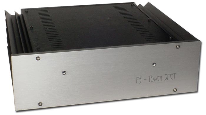
| Advancing the art. That requires a lot more than repackaging proven circuits. Or throwing designer parts and boffo face plates at them. Or hype marketing and hyper pricing. Advancement means following the dark paths previously avoided. It means doing something not done before. Invention in other words. Creativity. In audio amplifier design, product launches are rare and few between which feast on that forbidden tree. That's because audio isn't a particularly viable field to tender with genius in the hopes of harvesting the long green in this lifetime. Anyone with ambitions to reap the rewards of brilliance is far better off working in the IT or computer sectors or selling the military a more accurate self-guided missile with higher payload. But there are some luminaries in our field. Just think David Berning and Nelson Pass in the consumer audio amplifier sector, for example. Today's review focuses on the latter inventor, in particular his reintroduction of a previously extinct breed in consumer audio amps: the Power JFET amplifier. Being an artist rather than copy cat, Mister Pass of course wasn't content to simply revive the old and unnecessarily complex. Hence expect a few new wrinkles and novel simplicity not attempted before. To properly present the case, we'll let the designer explain concept and execution in his own words and take over again when it comes to the subjective review commentary: |
||||||||||||||||||||
 |
||||||||||||||||||||
| "There are two basic elements to an amplifier design – the parts you use and what you do with them. Of the parts, the active gain devices are the most important and critical. They contribute most of the distortion and their characteristics heavily influence the rest of the circuit design. The better the parts, the simpler the circuit can be. The more subtle the circuit design, the more you get out of the parts and the better the sound. Simplicity not only reduces the number of parts that the sound has to go through, it requires a design that maximizes the linearity of each gain stage and minimizes the feedback. For the last twelve years, I have been exploring power amplifier designs with only one gain stage (the Zen series ) in contrast to commercial designs using as many as nine gain stages. The simple amplifiers often don't measure up as well in demanding applications but when the speaker is easy to drive and the music isn't too loud, a simple amplifier often sounds better. To get these single stage amplifiers to work, I've been using power MOSFETs for gain devices. These were the only devices which had the characteristics to make a practical single-stage power amplifier - high input impedance; high voltage and current capacity; high gain. The Zen amplifiers were all Class A designs, both single-ended and push pull. And they all delivered about 10 watts or so. Some used feedback, some didn't. They all measured between .05% and .5% harmonic distortion at 1 watt. Power MOSFETs were chosen by default. You can't get a practical single-stage power amplifier from a tube. The gain is too low. A bipolar transistor has too low an input impedance. And there were no power JFETs on the market. JFETs, or Junction Field Effect Transistors, are routinely used in the input stages of the finest solid-state amplifiers and preamplifiers where they give very high input impedance, high linearity and very low noise. JFETs are often extolled in promotional literature for their "tube-like" qualities. To my knowledge, power JFETs as such have not previously made it to the market. In the 1970s, Sony and Yamaha offered a series of JFET power amplifiers using their own semiconductors but discontinued them after a few years. I have been told authoritatively that product reliability was an issue. Nevertheless, the amplifiers remain highly regarded for their sonic performance. Here is a simplified schematic of the five-stage Yamaha B1, which used low-power cascoded JFETs in the three front-end gain stages and also a fourth output drive stage which then drove Power JFET output transistors in Class AB mode. |
||||||||||||||||||||
 |
||||||||||||||||||||
Since then, JFETs have only been available as low-current, low-power signal devices. MOSFETs have become the dominant field effect power devices mostly because they make great switching devices in power supplies and such. It is possible to make power JFETs which are better in linear amplifiers than the current MOSFET offerings, but probably the market has been judged too small. In recent years, advances have been made in vertical JFET design which makes them more competitive in switching applications. As a result, power JFETs have been reintroduced after a 30-year absence. Earlier this year, I published the "Zen Variations #8 - the Power JFET Amplifier" and now First Watt is introducing the Model F3, at this time the world's only commercially available amplifier using power JFETs. Why power JFETs you ask? Don't we have enough transistors already? We do have lots of choices in devices but a power JFET brings some particular advantages to the table that we don't get elsewhere. First off, for comparable devices at a given bias current, we see that the power JFET has much less distortion. The original F3 circuit was designed with a MOSFET and comparing "apples to apples", the power JFET operated with one-fifth the distortion of the MOSFET. That's only the beginning. The JFET has much less distortion operated as if it were a MOSFET but it's not a MOSFET and has characteristics which allow for even better performance. |
||||||||||||||||||||
 |
When we look at the anode (or tube plate) voltage curves for devices, we see what I would call the "triode character" and the "pentode character". To the left is an example of the triode character. On a triode, for a given grid voltage, as the plate voltage rises the current goes up in an exponential fashion. |  |
||||||||||||||||||
| To the right is the pentode character. In contrast to the triode, the current tends to level out more with increasing voltage in what looks to be a roughly logarithmic fashion. It has a "convex" shape as compared to the triode's "concave" shape. A distortion-free linear device such as a resistor would have a straight line. Since no gain device does a perfect job of approximating a resistor, various techniques have been developed over the years to make them more linear. Another curve common to field-effect devices is the transfer curve of the device operated at a constant voltage across the device, as seen below. We note that like the triode curve, its shape is exponential in character . |
||||||||||||||||||||
Triode designers linearize the tube circuit by operating the voltage/current load line so as to get some cancellation between competing voltage (plate curve) and current (transfer curve) distortions. This can be done with either single-ended or push-pull circuits. The way it works is like this: For a fixed Grid/Cathode voltage, the current rises exponentially with Plate/Cathode voltage. For a given Plate/Cathode voltage, the current rises exponentially with Grid voltage. Both these curves look similar on paper. When you use the tube as an amplifier, these two curves oppose each other. While the gain is rising at higher voltage, it is also declining because of the reduced current. These two effects can be made to cancel, resulting in more linear performance. |
||||||||||||||||||||
 |
||||||||||||||||||||
| Designers will choose the voltage and current operating conditions to exploit a load line which is the region the tube traverses over its operating cycle. By carefully positioning the load line, tube distortion can be dramatically reduced. (Unfortunately, this works best for resistive loads and not as well if the load is reactive or has the wrong impedance value). That's all very nice for triode circuits but gain devices with pentode-type curves -- which include MOSFETs as well as pentodes -- cannot take as much advantage of this technique. While they have the exponential transfer character, their anode voltage curve does not cancel in the same manner. They must use different approaches, most commonly feedback. But as you look at the curves for these power JFETs, you can see a narrow region below 5 volts and 10 amps where the anode characteristic looks like a triode, so that a load line can be constructed which further linearizes the device. If we have a gain device that behaves a bit like a triode, then it is natural to try it out in a popular triode amplifier topology. For many aficionados, that topology would be single-ended Class A operation. 300Bs, 211s and their cousins operated single-ended and coupled to an output transformer have been held by many as the low-power musical standard. Single-ended Class A tube amplifiers are not very powerful and their measurements are nothing to write home about, but there is no denying that they have strong musical appeal to a sizable segment of the audiophile population. Getting the most linear performance from these power JFETs relies on a topology known as cascode operation. The JFET is operated with a Common Gate partner device which contributes so little of its own character to the output that it doesn't rate as a gain stage per se but shields the actual gain device from the output voltage. Cascoding makes the voltage across the JFET constant so gain variation due to fluctuations of Drain/Source voltage (the music) vanishes. Cascoding also dramatically reduces the need to charge and discharge the input capacitance of the JFET. Cascoding also allows a relatively low-power, low-voltage power JFET to operate in a high- voltage, high-wattage environment with little dissipation. The cascoding device acts as an umbrella, taking the heat while leaving the JFET completely controlling the current through the circuit. Freezing the voltage across the JFET lowers the distortion by itself but does not give us the most optimal load line for the device. For absolutely lowest possible distortion, the JFET must see some voltage fluctuation across its Drain and Source pins. For this purpose, I developed a modulated cascode topology (you heard it here first). This imposes a slight voltage variation across the JFET as a function of the current through the device. The advantage of this circuit is that the load line truly becomes a function of the output current, not the output voltage. This works better than the classic triode approach because it accounts for reactive loads or loads which are not the correct resistance. The F3 is set up so that the load line of the JFET can be adjusted with two degrees of freedom, tweaking the circuit to the individual character of the JFET. With this adjustment, the F3 gives about 0.01% distortion at 1 watt. This is a remarkable achievement for a single-stage power amplifier. The original Zen amplifier had sixty times that figure at 0.6%. |
||||||||||||||||||||
 |
Here is the simplified schematic of the F3. It bears a superficial resemblance to the Zen Variations #8 circuit, but it is not the same as evidenced by the higher performance of the F3. Being a single-ended Class A circuit, its characteristic is "second harmonic", that is to say the distortion curve is dominated by a second harmonic as seen below. |
|||||||||||||||||||
 |
||||||||||||||||||||
As you can see from the following curves and specifications, this is a good low distortion amplifier in the ordinary context of solid-state amplifiers and a phenomenally good single-stage amplifier. |
||||||||||||||||||||
 |
||||||||||||||||||||
| Distortion vs watts @ 8 ohms, 1kHz | ||||||||||||||||||||
 |
||||||||||||||||||||
| Distortion vs watts @ 4 ohms, 1kHz | ||||||||||||||||||||
 |
||||||||||||||||||||
| Distortion vs watts @ 16 ohms, 1kHz | ||||||||||||||||||||
 |
||||||||||||||||||||
| Distortion vs frequency @ 8 ohm, 1 watt | ||||||||||||||||||||
While much of the explanation here has used tubes as examples, I am not suggesting that I wish to emulate tube amplifiers as such. I want to give a basis for understanding the advantages of these new devices and the types of circuits that elicit the best from them. At the same time, you will hear some similarities, partly because there are similarities to the measured performance, and partly because both types of design have a similar philosophy and minimalist discipline. |
||||||||||||||||||||
 |
||||||||||||||||||||
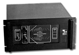
| I am mindful of what happened when MOSFETs first arrived, when mediocre designers simply threw them into the same old bipolar circuits that they had copied from the RCA manual and the marketing departments trumpeted how tube-like they were. They | ||||||||||||||||||||
| weren't. It has taken years for the reputation of MOSFETs to recover and for designers to put them into circuits where they are most appropriate. Power JFETs are remarkable new devices that offer some specific advantages and I fully expect them to take their place in circuits which uniquely address their qualities. I note that it was just about this date 30 years ago when Rene Besne and I sat down to listen to the final prototype of the Threshold 800A (shown above), which was my first commercial offering. Times flies when you're having fun."" - Nelson Pass Summary of the nominal specifications measured at 120V AC with a 25-ohm source and an 8-ohm load: Input Impedance - 10 Kohm Input Sensitivity - 627mV for 1 watt, 8 ohms Damping Factor - 8 Output power into 8 ohms - 15 watts @ 0.2% THD, 1KHz Output Power into 16 ohms - 10 watts @ 0.1% THD, 1 KHz Output Power into 4 ohms - 10 watts @ 1% THD, 1 KHz Gain - 13.0 dB Maximum unclipped output - +/-13 volts, +/- 2.5 amps Frequency response - 3 dB @ 1.5Hz, 70KHz Noise - 100 uV unweighted, 20-20 KHz Power consumption - 200 watts Fuse - 3AG slow blow type, 4 Amp for 120VAC/ 2Amp for 240 VAC Warranty - Parts and labor for 3 years, not covering shipping costs or consequential damages Arrival of our review loaner is expected in a few weeks. Time to harness the power of JFETs... |
||||||||||||||||||||
 |
||||||||||||||||||||
 |
||||||||||||||||||||