This review page is supported in part by the sponsors whose ad banners are displayed below |
 |
 |
In advance of releasing the design, I had people on the DIYAudio thread speculating about all the things I might be doing and so forth. At some point they got extremely close (at the end here I have a version that gives a nod to a feature one of them came up with). |
|
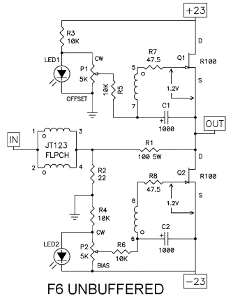
We've done some fill-in but it's still the same basic circuit. We are driving the input primary of the transformer as the input. With the feedback the input impedance is about 20KΩ at lower frequencies. But it has a fair amount of capacitance between the windings, in particular the one seeing the output voltage of the amplifier. So it's rather limited unless you have a low source impedance. If your preamp has an output impedance of 100Ω or less it's no problem but if it's 600Ω or 1KΩ, it's going to be real soft in the top end. This has a feedback figure of about 24dB which lowers the 'open-loop' distortion by more than a factor of 10. It also delivers a damping factor which is almost identical to the amount of feedback. That 24dB of feedback is equal to 16 times and when I measured the output impedance of the amp I got 0.5Ω - which is a damping factor of 16. |
|
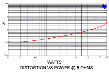
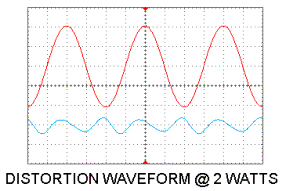
The amplifier maintains a second-harmonic character through the lower part of this region. You can usually tell a second-harmonic character because the distortion rises as the square root of the power. If it's 0.01% at 0.1 watt, it will be 0.1% at 10 watts. Here is the distortion waveform as seen through the Audio Precision analyzer on a scope. You can see the two traces, the output signal and the remnants of distortion and noise left over if you subtract the pure part of the sine wave output signal (magnified for easy viewing).
|
|
In the waveform of the distortion component, what you really want is a nice smooth character. And you want it as a low-order harmonic. Looking at this you see that it is dominantly second harmonic (twice the frequency of the undistorted sine wave). There's a little expansion added to the top of the original waveform (positive) and a little compression to the bottom of the original (negative). If you look at it carefully you can also detect a little bit of third harmonic. The interesting thing about this is that second and third harmonic character correlate to a lot of people's listening preferences. I recall Jean Hiraga's comments about liking amplifiers which have a particular amplitude relationship between second and third harmonic—and probably no higher harmonics—and it appears that he preferred it over purely second harmonic.
|
|
|
I don't think anyone has particularly improved upon that observation. If you're going to have some distortion then this is likely how you would want it. I can tell you that many of my amplifiers that have done well in the marketplace start out being dominantly second harmonic at low levels. With increasing power you start seeing some more third harmonic and somewhere below clipping the distortion is dominantly third. We are talking about human ears here. It's useful to remember that the ear is not a microphone and the brain is not a tape recorder. We have very complex neural networks that in many ways defy our efforts at simple analysis. A lot of my thinking on this subject is merely the result of observation. "This is what I like, this is what I perceive." It is thus difficult to describe further.
|
|
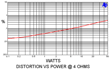
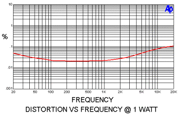
Here's the same amplifier's distortion into 4Ω. It actually does quite well. Into 8Ω it does about 30 watts and into 4Ω it gets up to 50 watts, making it better at driving lower impedances than many of my other little amplifiers.
Question from the audience: "Just to clarify, that's 50 watts out of one pair of SITs?"
These aren't SITs but regular power Jfets - SemiSouth SJEP 120100. The SITs are a more exotic form of a Jfet with a character more like a triode than pentode. There are frequency limitations to transformers at the low frequencies where they lose some inductive coupling as well as losses at the high frequencies due to winding capacitance. Here is the distortion vs frequency plot: |
|
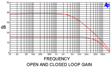
Here's the open loop and closed loop gain vs frequency of the amplifier - 38dB or 39dB of open loop gain rolling off at 5kHz. With about 24dB of feedback we get 15dB gain rolling off at about 50kHz.
|
|
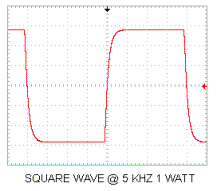
Here's the 5kHz square wave at 1 watt. It's not real fast but nice and clean, with no ringing or anything nasty. It's not exceptional in this regard but better than your CD player.
|
|
A problem that we will now address is that the input capacitance of this amplifier is relatively high. It requires a low source impedance in order to get acceptable frequency bandwidth. 100Ω is fine and not much improvement is available if you provide lower than that. Some sources don't provide this, particularly 'passive' preamps and a number of solid-state and tube preamps.
|
|
|
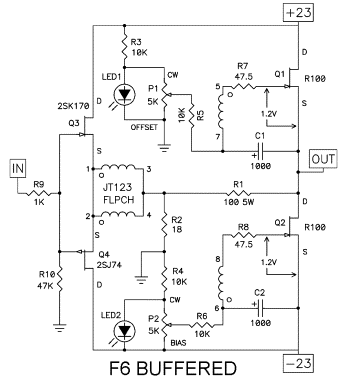
Here is one solution to this issue—familiar to many by now—a buffer formed by the pair of Jfets Q3 and Q4 arranged as followers. They self-bias conveniently. If you tie their Gates and Sources together, a known amount of current (their Idss) will run through them. We put a resistor to ground at the input so there is no confusion without a source connection; and a 1KΩ resistor in series with the Gates because that's just smart. Without an input resistor you would inevitably find some system or cable interaction or something that would create stability problems for you. The buffer provides a 47KΩ input impedance for the amplifier and a 25Ω or so source impedance to drive the transformer. |
|
This is the circuit that we have in the working display down the hall. The buffer didn't make any significant difference in the measurements or the sound as compared to a low-impedance source but here is the option for when you need it. There are those who would correctly point out that you can run lower distortion if you put some resistance on the Sources of the input Jfets because they would then not be running near their Idss figure. What happens there is that the Gates can start drawing a little current on peak inputs. I tried it both ways and didn't have any issues either way so I left those resistors off. However, if you have Jfets with high Idss values then some resistances on the Sources would lower the bias current and thus the heat dissipation of these transistors.
In this circuit the input Jfets were chosen for Idss at 8mA or so but you can get them with Idss up to 20mA, which times the 23-volt supply will exceed their 0.4-watt rating. Or you might try some other Jfets with higher Idss or higher supply voltages. If you find that you need to degenerate the input Jfets with some resistance, you will find that there is little or no performance penalty for small resistance values.
|
 |
  |
 |