This review page is supported in part by the sponsors whose ad banners are displayed below |
 |
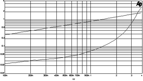 |
"These are the lowest distortion big power transistors I have seen. To give you a sense of the difference, this graph shows the distortion between two different transistors operated under identical conditions in an F2 amplifier. Here we see the popular IRFP240 N channel Mosfet (top curve) versus a SemiSouth SJEP120R125 N channel JFET, both operated in Common Source mode, biased at 10 Volts DC and 2 amps by a constant current source and driving an 8-ohm load without feedback. |
|
"Zowie! The JFET is about 20dB better. At the higher power level in this particular circuit, you will see that the difference declines. That is simply the effect of the triode-like character of the JFET at lower voltages across the device – you can take care of that with a couple of extra volts on the supply. And with a 1200-volt rating, you have some margin to burn, in fact you could stick this in where a 300B used to go. Not that I would do such a thing. Also, the distortion remains much lower at high frequencies as well. This part has about half the input capacitance and about 2/3 the reverse capacitance of the IRFP240 and the value is more linear so in typical amplifiers, we see about a quarter of the distortion due to junction capacitances."
|
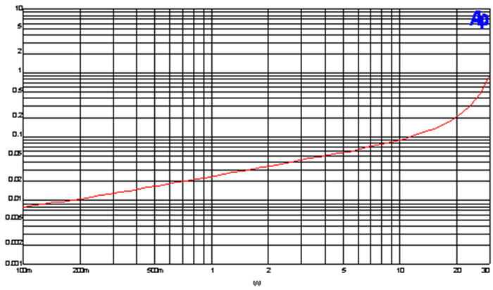 |
Here's the distortion into 8 ohms at 1Khz from 0.1 watts to 30 watts.
|
|
|
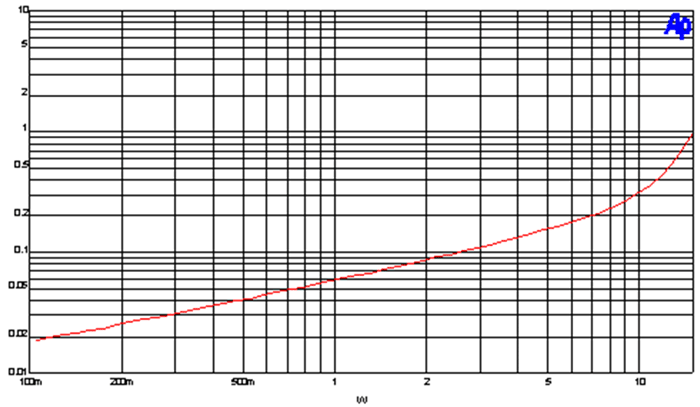 |
Here's the distortion into 4 ohms at 1Khz.
|
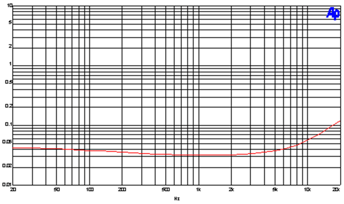 |
Here's the distortion into 8 ohms at 1 watt from 20 to 20Khz. |
|
Here's what that second harmonic distortion looks like. |
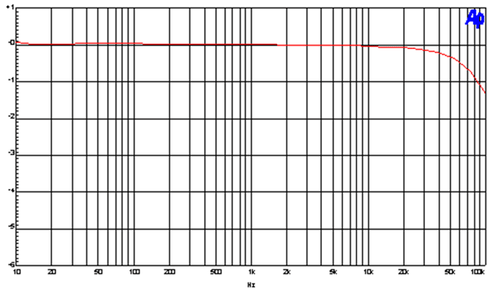 |
Here's the frequency response from 10 to 100Khz |
|
Here's the square wave at 20kHz.
|
|
|
 |